Recently I confirmed that a smoke detector can be useful. I forgot a sauce on the stove and it burnt. I left the flat and luckily heard the smoke alarm from outside!
So, to be safer in the future I wanted to make a network-connected smoke detector that reports to my home-assistant instance. From there it can notify me via SMS or flash lights or sound an alarm.
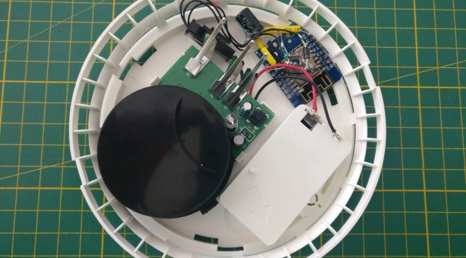
By chance I found a smoke detector at IKEA. I needed to see if it can be hacked.
Good news! It can! 🙂
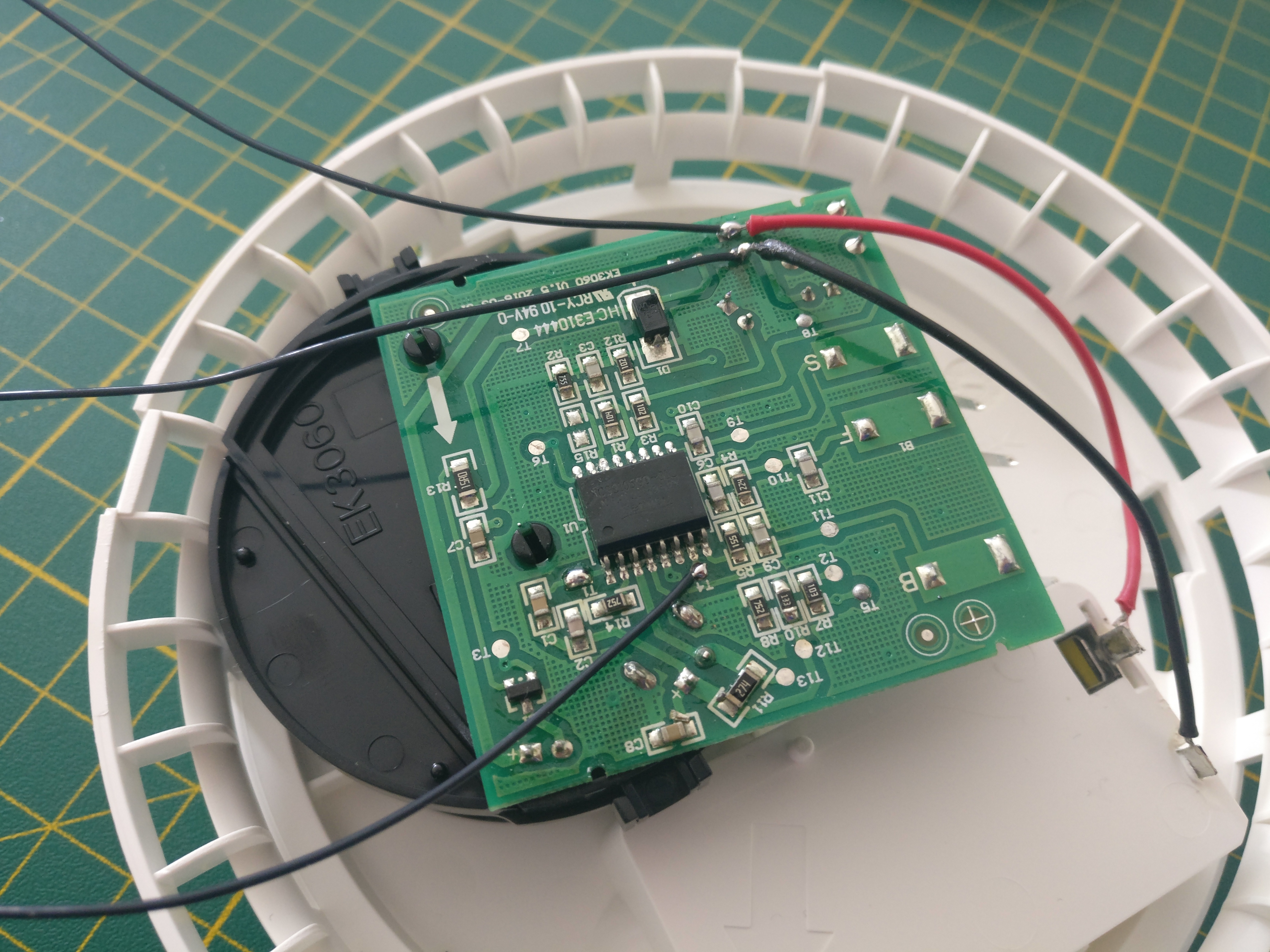
It turns out the micro controller that is used (CS2105G0-S12) offers a nice pin (Pin 7 – I/O) to be used for external electronics. Conveniently the PCB has a test pad (T4) that one can solder to.
On the interwebs™ I found a design that uses the internal battery of a smoke detector to power an ESP8266. I modified the layout to work for a Wemos D1 mini. Switching the transistor to a Mosfet, allowing more current to pass, was the fix.
The layout shows how the Wemos D1 mini is powered. It runs MicroPython, only when the alarm goes off. An alarm must be active for about 20-30 15 seconds for a message to go through. The wifi module connects to a local wifi network and sends a MQTT message to a pre-defined channel.
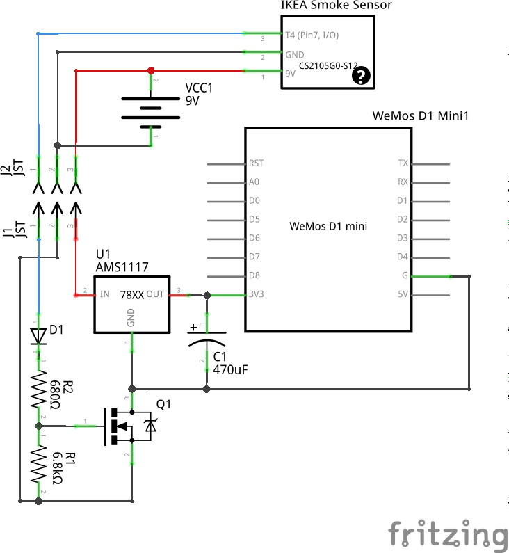
The I/O-Pin 7 of the smoke detector is high at 9V when smoke is detected. The Mosfet will be switched on and the battery now powers the D1 mini as well, allowing notifications via network. The ESP8266 on the board is flashed with MicroPython. The script connects to the local wifi and notifies home-assistant via MQTT that smoke is detected. Home-Assistant does the rest.
The source of the script can be found here on gitlab or on github.
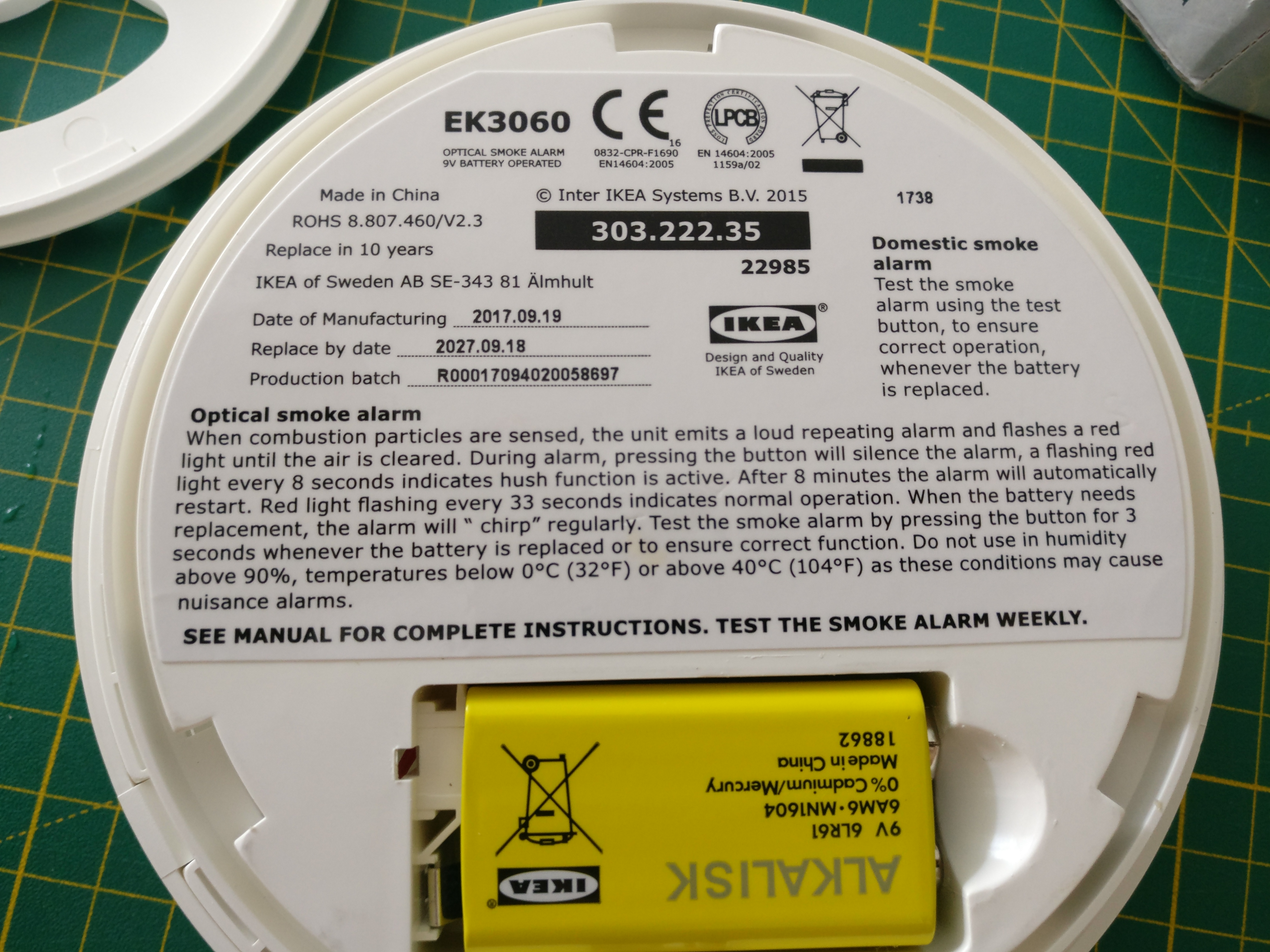
Battery update: Since November last year to beginning of October this year, the battery level dropped from 8.8V to 8.2V. Considering that the level is probably good until a level of about 7 Volts this should give the sensor a run time of a little less than 3 years. I did test the sensor several times in this time span, so this could be another factor for more battery drain.
The battery life time should be one year according to IKEA.
25 replies on “Ikea DIY Smart Smoke Detector…”
This is really cool. Do you have any experience yet what is the battery life of this combination. You could use the deep sleep option of the ESP8266 and only wake it 1/hour or if there is a smoke alarm. See https://openhomeautomation.net/esp8266-battery
The deep sleep is a nice feature, it’s not needed though. The idea of this circuit design is that the WIFI module is not powered at all until smoke is detected.
This should lead to a battery run time that is comparable to the original run time. Only when smoke is detected the battery consumption is higher.
The drawback is that we are not able to connect to the device. The device also cannot check for the battery status or have another sensor attached to it (temperature, etc). It would not be powered.
It can however report the battery voltage once the alarm goes off if you use a voltage divider and the Wemos Analog Pin.
The use is pretty limited though, since the I/O pin of the smoke alarm, meant to make all alarms in a building go off simultaneously once smoke is detected somewhere, is not being pulled HIGH when the detector just beeps a low battery warning. I imagine you can check the battery voltage whenever you press the smoke-detector test button 🙂
I implemented it anyway in my version (inspired by flo’s):
https://wp.realraum.at/2018/08/wifimqtt-smoke-detector-with-5yrs-battery-and-esp8266/
[…] Read about Flocx’s current project, a battery-saving WIFI+MQTT-enabling cheap smoke-detector here: https://blog.flo.cx/2018/08/ikea-diy-smart-smoke-detector/ […]
Did it fit back into the casing?
yes, it did! 🙂
Great! I’ll give it a shot myself as well then.
The D1 mini has an on-board voltage regulator and, according to the datasheet, works with up to 12V. No need for the AMS1117 (unlike with ESP01’s). Why not simply hook up T4 to the D1’s 5V-pin?
The research I did, back then, showed I needed it.
A quick search now shows that the D1 mini uses the ME6211 and it has an operating voltage of 2V to 6V. so the 9V battery would be too much…
If you have a datasheet that says otherwise, you could try it.
Hi there,
I just opened a Family Shield photoelectric smoke alarm, purchased from Bunnings in New Zealand for NZD 7.89
https://www.bunnings.co.nz/family-shield-photoelectric-smoke-alarm_p08909655
Inside is the same CS2105G0-S12, but pin 7 is brought out to a test point labelled TP7, which is a little hard to get at as there is a small metal shield sitting about 3mm over it (and half of the chip).
Do you have a part number for the MOSFET you used? Also, why switch the ground line instead of the power line, and why not just power everything from pin 7? I suppose it may be current limited, but I couldn’t find what the limit was in the datasheet.
Anyway, great project. I will build one, although there is very little space inside the enclosure for this model.
Or a 3V3 regulator with enable pin? Although those are generally ~EN, so you’d need an inverter somewhere.
Depending on what part you find you could also do that, however if it needs ~3V to EN it is probably unpractical.
But there are many ways to skin this cat: Realraum, the local hackerspace, did a similar mod: https://wp.realraum.at/2018/08/wifimqtt-smoke-detector-with-5yrs-battery-and-esp8266/
The great thing about the IKEA smoke detector is, that you have plenty of space in the housing. Also there is only one PCB, which makes soldering onto it easy.
The MOSFET is a LU8743.
Regarding switching the ground: I think the reasoning was, as you suspected, the current limiting to the MOSFET. the voltage regulator and the Wemos D1 mini take the load, and all the MOSFET has to do is turn off ground. The MOSFET could take either option I think.
Hi,
Thanks for the quick reply.
I found a bit of information in the comments of the YouTube video, and a couple of other places.
I happen to have one of these boards:
https://m.aliexpress.com/item/2038556861.html
It is based on MP2307, which has an EN (active high) pin, so it might work. Based on the datasheet it has a 1uA standby current. I should get away with that power module connected to the battery, and EN connected to pin 7, then the output connected to the Wemos.
I found a space for the Wemos on top of the battery housing. 🙂
It gets better! The “official” Wemos dc power shield has an MP2359 regulator on board. This has an EN pin. The pin is connected via a very visible and accessible 100k resistor to Vin, so could be hacked to connect to pin 7 instead.
The downside is that the Wemos power board is quite large compared to some of the other boards on AliExpress. The upside is: I have one.
PS We don’t have Ikea in New Zealand. Sore topic. 🙁
PPS Your timeout on this comment form is a bit short.
Ok. It works!*
Current consumption of the alarm is just under 4uA, but it jumps up occasionally. The alarm manual says around 12uA, which will be its average consumption over time.
I modified the Wemos power board as follows. First, I removed the 2.1mm coaxial power socket to reduce overall height. Next, I disconnected the “high” end of the 100k resistor that feeds Vin into EN on the regulator by cutting the PCB track. Finally, I soldered flying leads to the 100k resistor, Vin, and GND. This makes the board into a normally-off 5V regulator. The 100k resistor is retained as it limits the current into the EN pin.
To connect to the alarm I soldered the three leads to the positive battery test point (Vin), the negative battery test point (GND), and pin 7 test point, TP7 (100k resistor).
So, the battery is connected to the Wemos power board, which is controlled by pin 7 on the alarm. When pin 7 is high then the power board outputs 5V to the D1 Mini Pro. The 3V3 regulator on the D1 Mini Pro then powers the chip.
Current consumption is just over 4uA when the power board is connected, so it adds about 1uA, as indicated in the regulator datasheet.
* The Wemos starts up and flashes its LED, but I don’t have microPython loaded. I’m sure it will work however…
Hi,
I think 20-30 seconds is kind og long time to get alerted, a lot can happen in 20-30 sec in regards to fire. What is the reason it takes so long time ? Why can the esp not send an alarm right away after the fire is detected ?
/donnib
It takes so long to connect to WIFI.
I did just stop the time: it takes about 15 seconds.
that’s not that bad. But keep in mind, it alerts you acousticly right away. The remote alert takes 15 seconds.
Still 15 seconds is long time. I’d like to use this in the garage and i am not sure i can hear the alarm from there so i’d like to get very fast alerts. I read online that others can get the time much lower, few seconds or even less by tweaking settings for example using static ip and remembering channel the network is on. Also above you write that the alarm must be active for 15 s for a message to go through but is that really true ? It should rather be that it wakes the ESP when the alarm goes then it’s takes 15s for the message to get to you. If you quickly release the test button you should still get an alert but after 15s right ?
It’s not just a wake. The smoke detector enables power, and must be on to do that. a wake could be implemented but uses more power, as you need to provide power to the ESP for it’s deep sleep and wake up cycles.
Ikea now has a different smoke detector ;
https://www.ikea.com/no/no/p/vakta-optisk-roykvarsler-20281886/
Does anyone know if it has the same pin?
I have some different smoke detectors, but I’m not sure how to check if they have a I/O pin with test pad (high/low?) Any tips?
Buy one, and look at it. That’s what I did. I looked at the chip they use and from the spec sheet I saw that there was a pin that enables external devices. I guess it might be just a design change on the skin. the inner assembly might have just gotten a minor upgrade (but that’s speculation of course).
Hi!
Thank you for the post!
I’m trying to recreate the build with some changes.
And only now I see that T4 is giving out a 9V signal. So I get false positives from time to time.
Do I need to drop the signal voltage through a voltage regulator as well?
Do I need to use battery 0 as ground?
I do have hard time measuring the signal voltage though – I connect black tip to the battery – and the red one to the T4 and see 0V.
Thanks!
Can I connect GPIO2 of my ESP-S01 directly to the I/O of the CS2105G0?
[…] are a couple of useful blog (this and that) posts that I started […]